Pic16f628a Serial Programmer
A series of basic assembly language programs for the PIC16F628. Includes programs. Using a Microchip PIC with TLC548 Serial. Programming PIC16F84A-PIC16F628A.
Looks nice, but I am looking for something I can make myself. I'm learning to make PCBs and read schematics. The JDM type I built I just can’t get to work right. I can erase it but not write to it with icprog.
I can’t get winpic to even initialize it. I went back over my schematics but everything looks right. I guess I just can’t work the programs. I’ve tried everything I may have overheated something during the solder process (My pen is a 40 watt) I may have to order something like the inchworm but I'll try another time or two and prove to myself I just cant do it first.
Click to expand.Heh always helpful eh. Crisis Core Final Fantasy Vii Download Ita Csodak. Theres loads of posts regarding the 'verify failed at address 0000h' with the JDM, try searching the forum.
This error comes up if 'anything' is wrong.so its not exactly useful for debugging.all it means is IC-prog is attempting to send out data, but when it reads from the PIC, it doesn't get anything, as that is its only source of feedback to check if its connected or if it can communicate. IC-prog has the ability to test the control lines so I would check the following: 1) make sure the VDD to the PIC is at least 4.5V. Should be 5v but anywhere between 4.5 and 5.5 sohuld be fine.

2) Check the voltage on the MCLR pin (pin 4 on the 628A), form memory I think the minimum voltage to get it into 'programming mode' is 12.7V, sohuld be arround 13V. It could either be hardware, or software. XP/vista don't like programs big banging the serial port and you may need some sort of utility. I believe this is all covered on the IC-prog website.

When you checked the voltages did you check the boxes in the JDM hardware debugging dialogue? I could be wrong but I seem to remember IC-prog doesn't power the chip properly when it is not programming it.
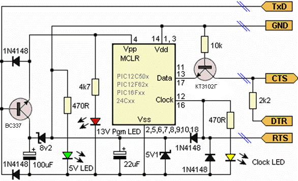
Failing that, I believe your serial port can't provide enough power/voltage for the programmer. Laptops especially have this problem, as do new computers with serial ports, because the days when RS232 were +/- 12V are gone, most only output about +/- 7v ish (that goes for USB-RS232 adapters too). Many programmers use an external power supply (15v) which can provide the 13v for MCLR, and then use a regulator for the 5v.in this case, the JDM style programmer simply switches these voltages, rather than actual;ly produce them from the power from the serial port, generally much more reliable. I hate to say it, but I would cut your loses and buy a PICkit2 or a copy off ebay The chinese copies/cloines are very cheap, work with USB, and support many chips, worth it if you are planning on promgramming PIC's for a while. Could you provide a schematic of the programmer you built? There are many variations of the JDM, some more reliable than others. Hi, I took a look at the schem on the site (the one in the zip file) and yep, its a stock JDM.
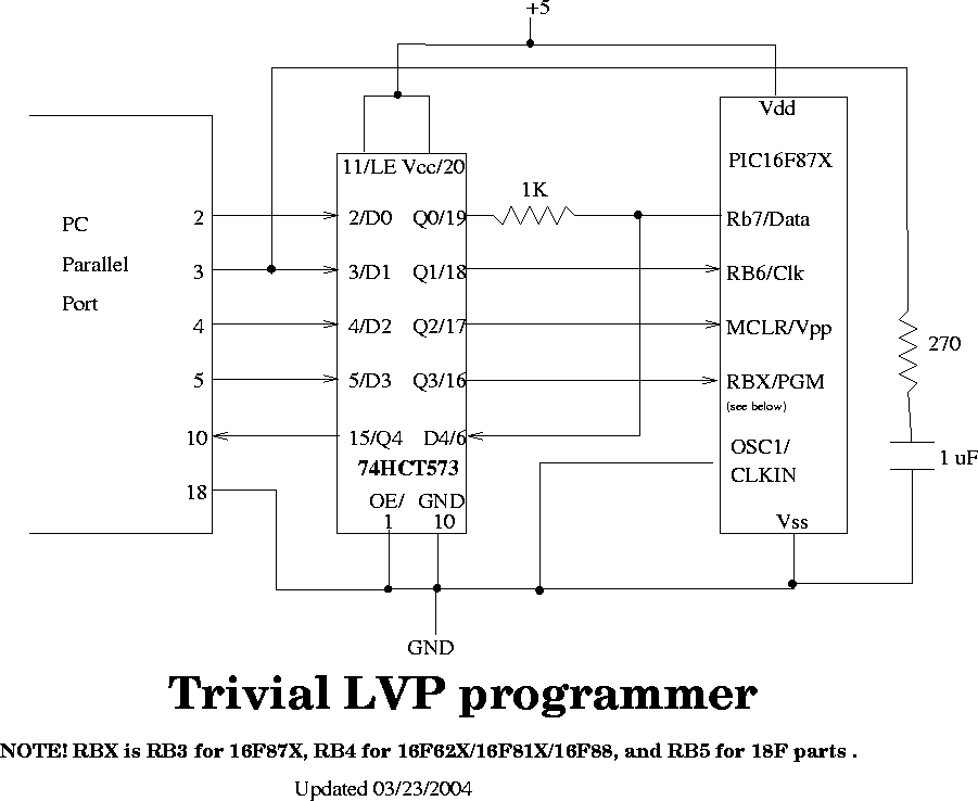
As Nigel rightly pointed out these are woefully unreliable. If you can, try this simpler version: I don't know why but when I started programming PIC's, the above version worked, when all others failed. Although, it does assume that your serial port can output +12.7V from the tx line to the MCLR pin, which as I said before, isn't usually the case these days.
This site has a good 'debugging' section for the JDM. Then of course theres the software problem.
IC-prog cannot always access the serial port under win2000/XP (god knows about vista) so there are some utilities that help it along. (xport?) You must try to find out what is causing the problem, as the 'verify failed at blah blah blah' error isn't at all helpful.
I usually start with hardware, as you have done, checking voltages etc.then software. Quite a good USB powered version is this: You can replace the USB connector with a 5v supply, it generates (rather poorly I might add) the 13v via a voltage multiplier, regulated by a 13v zener and silicon diode, to make 13+0.6 = 13.6v. Epub Reader For Windows Cracked Background. This is switched by an optocoupler (can be replaced by a transistor as I did). That should help. Of course there is no point in building another JDM, but if you one really doesn't work after all that, consider buying one. They are a hell of a lot cheaper than you might think.